CP SERVICES
CIPS – Close Interval Potential Survey
Traditionally, the effectiveness of cathodic protection of pipelines is determined based on potential readings obtained from Test Posts regularly spaced 1-2 kilometers apart. The CIPS measurement involves measuring and recording pipe to soil potential every 1-1.5 m, whilst walking along the pipeline route. The measured values and data considered important will be stored in the memory. In a further processing step, a potential diagram is generated from these data Based on the diagram, the efficiency of cathodic protection can be determined for the entire length of the pipeline.
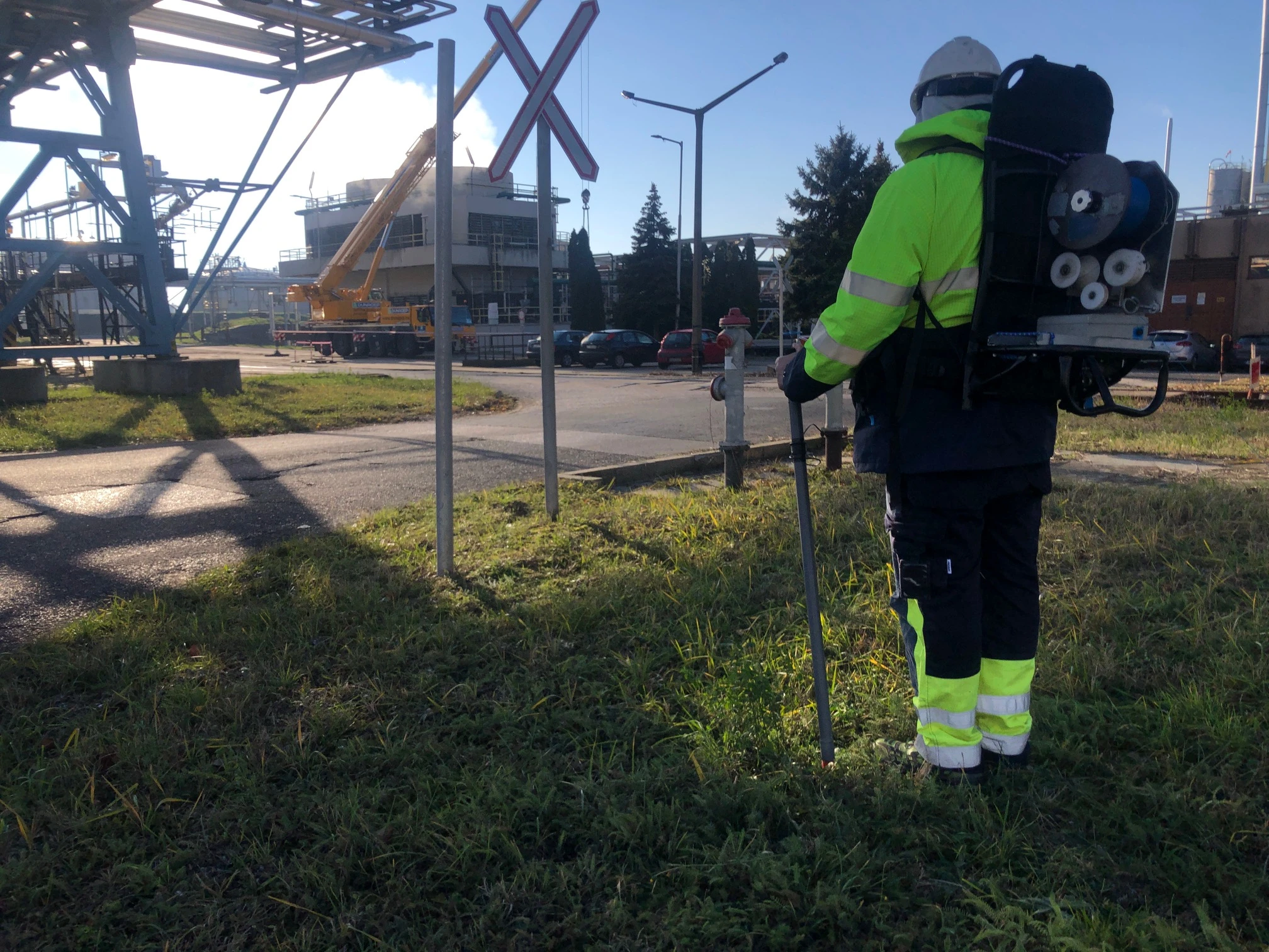
DCVG method for locating coating defects
The DCVG method is directly related to the cathodic protection of pipelines. From the impressed current cathodic protection system DC current flows into the coating defects causing a voltage drop in the soil. This method is also effective in the case of pipelines without cathodic protection when using temporary anodes and CP stations. When installing a new pipeline, it is recommended to carry out a DCVG Survey immediately after laying the pipeline, allowing the contractor to eliminate any protective coating defects still under warranty. The DCVG method is also suitable for the coating inspection of underground storage tanks.

Combined CIPS+DCVG intensive measurement
The simultaneous application of the CIPS and DCVG methods has numerous advantages over other diagnostic solutions:
- a structure/corrosion potential value is assigned to every coating fault position
- these measured (real) values serve as a basis for the calculation of coating defects (%IR)
- potential measurement takes place directly above the pipeline
- a given survey is performed by only one team
- simultaneous measurements ensure the comparability of CIPS and DCVG data, as soil properties, cathodic protection characteristics and human factors are the same at a given location and time;
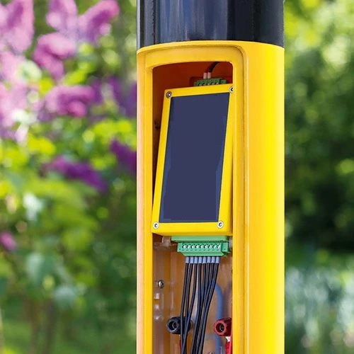
- based on the data measured and stored simultaneously by the measurement data logger a unified, printed chart is generated to repo
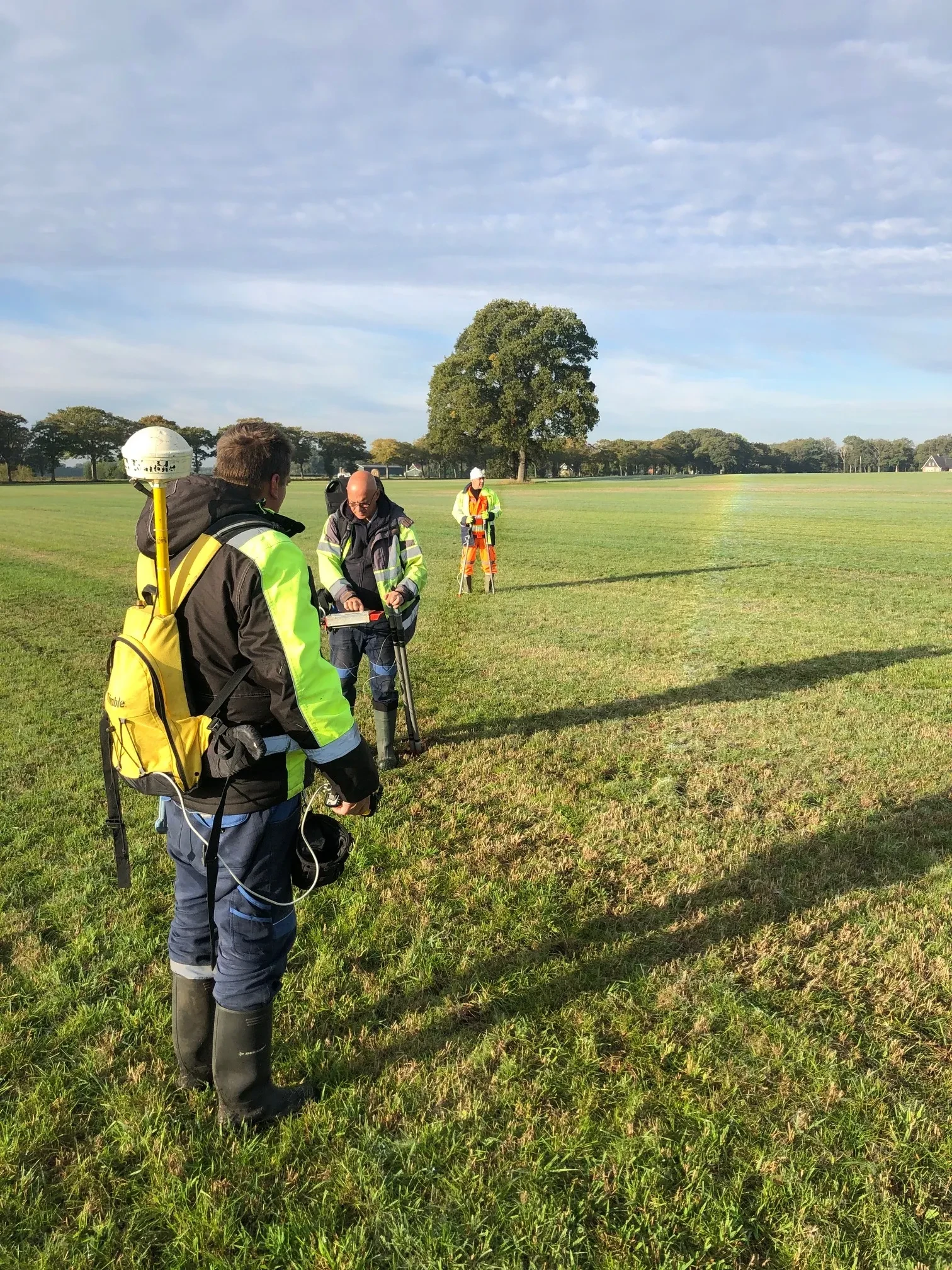
Positioning by GPS technique
During pipeline surveys, it is of utmost importance to precisely locate the structures and coating defects on along the pipeline route. Over a distance of several kilometers this can only be achieved with GPS equipment. It is particularly important to determine the exact location of coating faults so that if excavation work is required, the costs of expensive heavy machinery can be significantly decreased.
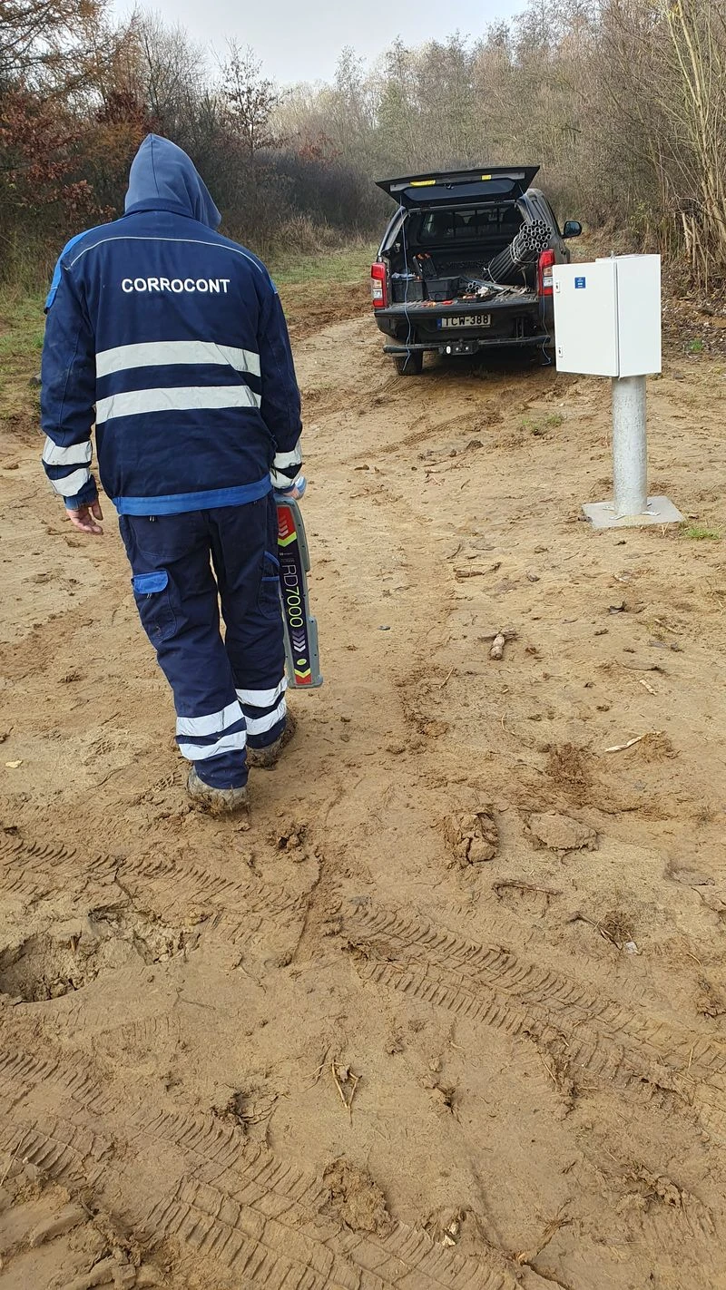
Pipeline Locating and Depth Measurement
Accurate pipeline location is essential for CIPS/DCVG surveys. In many cases, several pipelines run parallel and close to each other underground. CORROCONT applies high precision pipe locators based on advanced technology to locate pipelines and to determine how deep they are. Our techniques enable a buried pipe to be reliably located and identified from the ground surface, providing a depth of cover reading without the need to dig a hole or penetrate the ground.
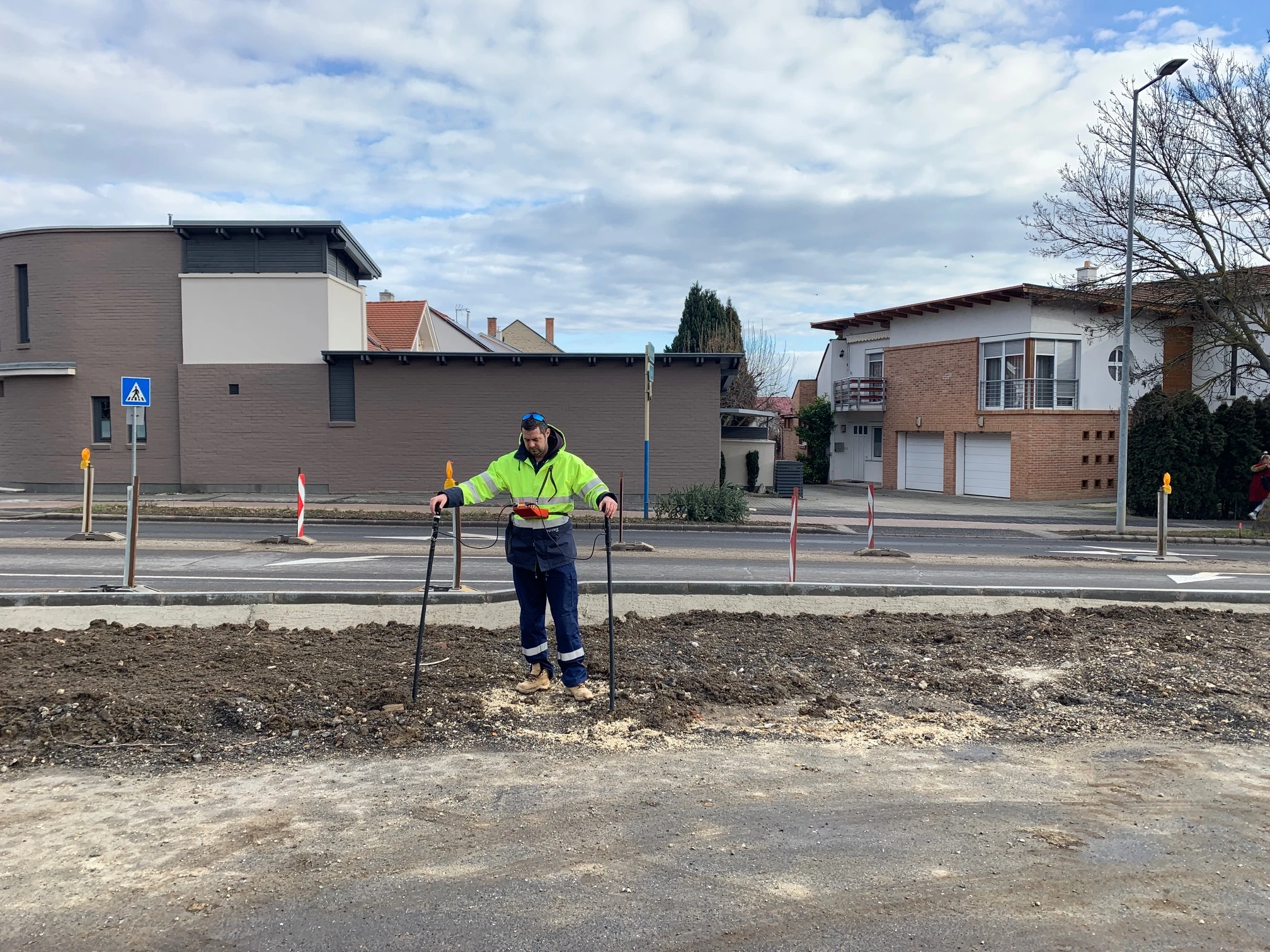
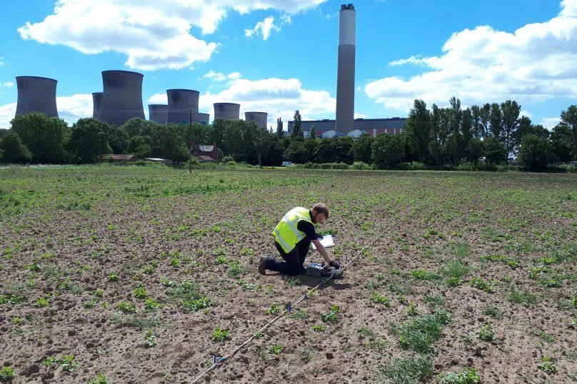
Soil Electrical Resistivity Survey
In site soil resistivity measurement is used to determine the aggressiveness of the soil. At CORROCONT, both the “Wenner four-pin method” and the “Electromagnetic method” are used. Soil corrosivity evaluation is based on NACE, BS and EU classification. Soil electrical resistivity indicates the relative capability of the soil to conduct electrical current and it is a main indicator in determining corrosiveness of the soil.
Stray Current interference testing
Especially stray currents arising from DC train, AC power lines and foreign CP system. Static CP survey is used to detect these dangerous interferences. All cathodic protection systems make currents flow through the electrolyte in order to achieve a certain protection level for the protected structure. These currents may cause earth current corrosion to structures due to neighbouring structures.